Modeling the Donjon of Etampes (Part II)

An update to the model.

The stairs’ vaulting got an overall modification as they first followed the slope of the staircase but now rise by step, which is more consistent with the style of that era and allow for a proper vaulting of the stairs, although I haven’t seen the actual remain of the tower so I cannot confirm that it is the case in reality. If anyone got some picture of information about that and anything else concerning the tower I would be happy to know.

Adjustment of the stair case vaulting.


Then, most of the arrow loops and windows are done with  one or two exception, most notably a window between first and second floor which is nowhere on any plan but appears on a picture I found on the net.


Most windows are done.
Inside view

I also started modeling the base of the columns of the great hall (second floor) as well as the chimneys.

Chimney and column base.


The top of the tower received the supporting walls for the roof and some basic timbering to support the floor.

Support wall added and some timber for the floor.

Lastly, I fixed the spiral staircase with the rest of the walls and had the steps match the floors. For this, since I do not know how many steps nor their height, I used a fairly common step size for that era, about 20cm, and used the indication of VLD in his plans that usually show fairly accurately the start and stop of the stairs at each level. Then, I tweaked the height of the steps to match start and stop points.

I still have to fix the entry of the tower, which is entirely missing nowadays and poorly documented (obviously, since it was long gone before anyone would think of documenting the site) and of course build the roofing. But that’s for an other time.

Cheers,

Lionel

Modeling the Donjon of Etampes

While coming across the description of the donjon of the castle of Etampes (France, Essonne), also known locally as the Tour de Guinette, and finding some plans and photos, I thought it would be a nice break from my C# learning endeavor. So I decided to go back in Blender to model the tower, following the plans quite rigorously, with the most possible details while keeping the polycount as low as possible.

Quickly, I ran into several problems. First, as usual, modeling anything curved with intricate geometry quickly becomes complicated if you want to respect proper geometry and keep the number of vertices on the low side. Second, they were different plans and projections of the tower, but they were not all consistent with each other, and since I didn’t want to make a fantasy structure, I had to do more research and try to sort out why those plans wouldn’t match and what would be the best interpretation to come up with. Unfortunately, I don’t have the opportunity to actually go to Etampes and look at the remaining structure of the donjon to help me make an educated guess, but thank Internet, there are a few pictures out there that came into great help. Especially the pictures of a fellow who flew a drone right above the tower looking downward. Third, while not so surprising, some actual features where not documented at all, but could hardly be left out of the model without compromising my initial goal.

So, I spent quite some time looking at the pictures, the plans, the projections, trying to make sense of it the best I could. The fact that the tower is heavily ruined nowadays with some parts entirely missing doesn’t help but in those areas hard to reconstruct, I resorted to make my best guess while respecting the period architectural style (XII century mostly). A lot of researching and reading later, this is what I came came up with so far. It’s not finished yet but it’s on its way.

Modeling the crenels.


Modeling the crenels was a tricky part as they are closed with an arch that is itself cutting through two concentric circular wall faces. I could have make it a lot simpler by connecting all the edges of the arches on the sides of the crenel but doing so would create some odd shading.

Some crenels, connected together with merlons.


My initial approach was to lay down the structure of the parapet flat from the top and then to extrude it, but it created a huge problem later on while trying to carve the arches in the crenels because of the concentric nature of the parapet.

View from the top, without any floors.

This parapet is base on Viollet le Duc restitution of the tower, but VLD being VLD, it is not exempt of a bit of, let’s say, idealism. As we can see on probably the oldest known remaining representation of the donjon in the Très riches heures du Duc De Berry (XV century, lower left corner in the picture above) the parapet was represented without any arching whatsoever. But I decided to model the VLD proposition regardless as it was more challenging and, let’s be honest, a lot more appealing visually. I might model something closer to what it might have been later on just for the sake of realism.

Closer look from the top.

The arches inside the tower which held the top floor and the roof are not there anymore but traces of it are clearly visible on the walls to this day.

The donjon of Etampes, unfinished yet, with windows and doors geometry sticking out.


The guts of the tower.
The tower’s geometry so far.

At this time, the geometry is separated in several pieces, one per floor at least, one for the external shell, and one for each important additional feature that are not yet completely adjusted, like the spiral stairs, columns, ceilings etc. This makes the whole process of editing much simpler and easier.

The inside with backface occlusion.
From above.
From above, backface occlusion.

Cheers,

Lionel


Preparing a new wall texture for the mansio of Khirbet es-Samra

Taking a break from Qumran

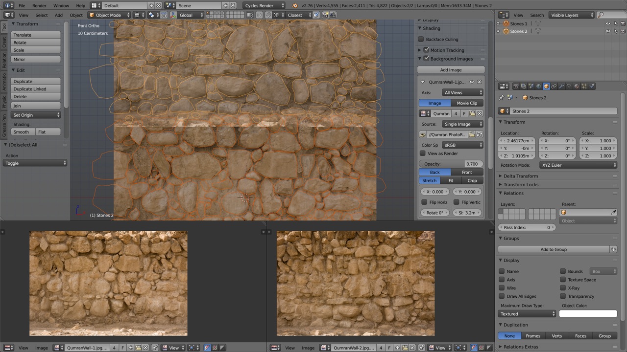
I went back to the model of the mansio of Khirbet es-Samra for which Jean-Baptiste Humbert, archeologist, asked me to make a model. The current model, well under way, uses a wall texture of which none of us are really satisfied. The obvious problem is that the structures on site do not have any significant wall left. It’s mostly razed to the fondations and therefore do not provide any significant way of evaluating the kind of wall that once stood there. But a good starting point is to look at the much more substantial remains at the nearby Khirbet es-Samra, which are believed to incorporate the raw materials removed from the mansio.

One stone at a time

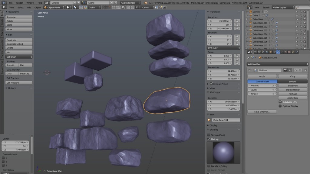
Based on the pictures of the Khribet, I started to model and sculpt some stones with the same technique I used for the stone wall texture of Qumran. It is a very time consuming process but to speed up the work, I decided not to only sculpt the front and side faces, leaving the back side untouched, but rather to sculpt the stones entirely. Thus, each stone can then be rotated on its six faces to create six variantes, and since I do not have to conform strictly to any given pattern, I can then use all these variantes to rebuild a similar wall structure as seen on the reference pictures.

01


Building the wall

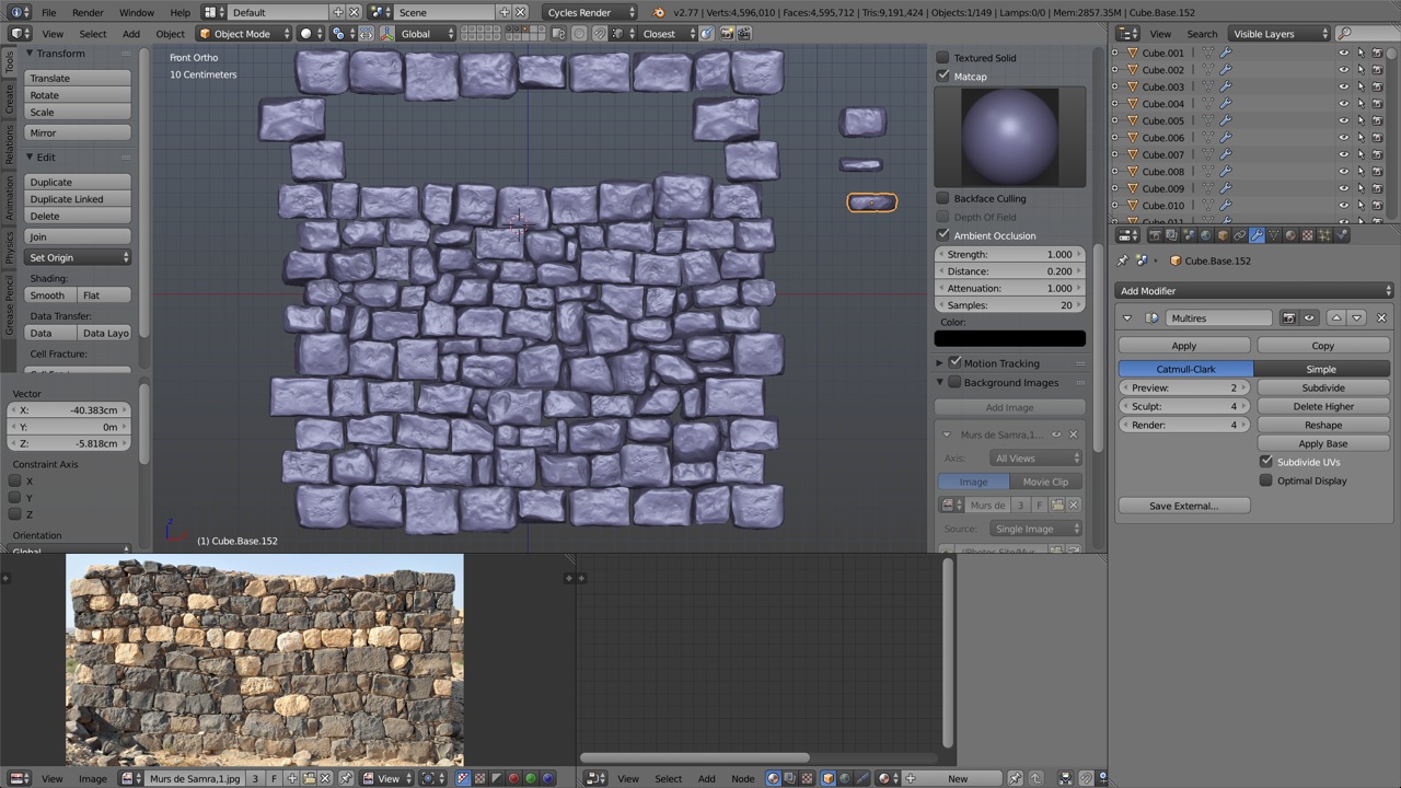
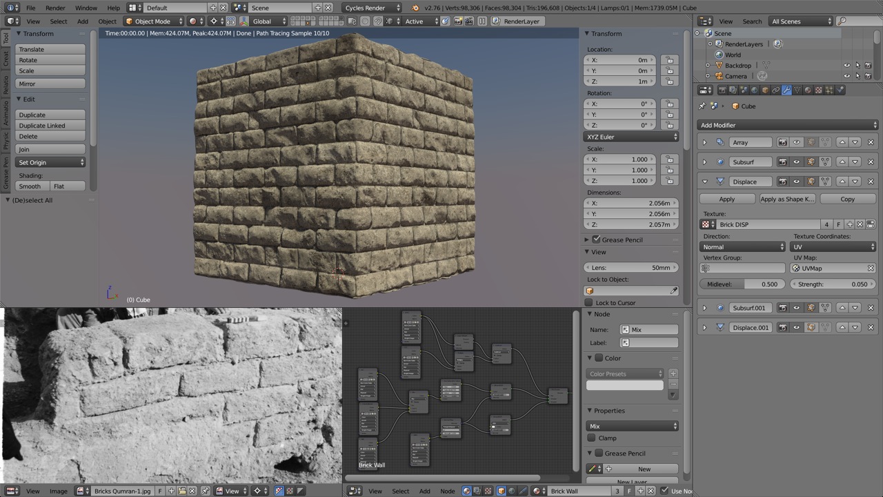
After having sculpted about fifteen stones of varying shape and size in conformity, more or less, to the reference pictures, it was time to duplicate each one five times and rotate them so that each duplicate shows a different face to the camera. I then had 90 stones ready to be placed.

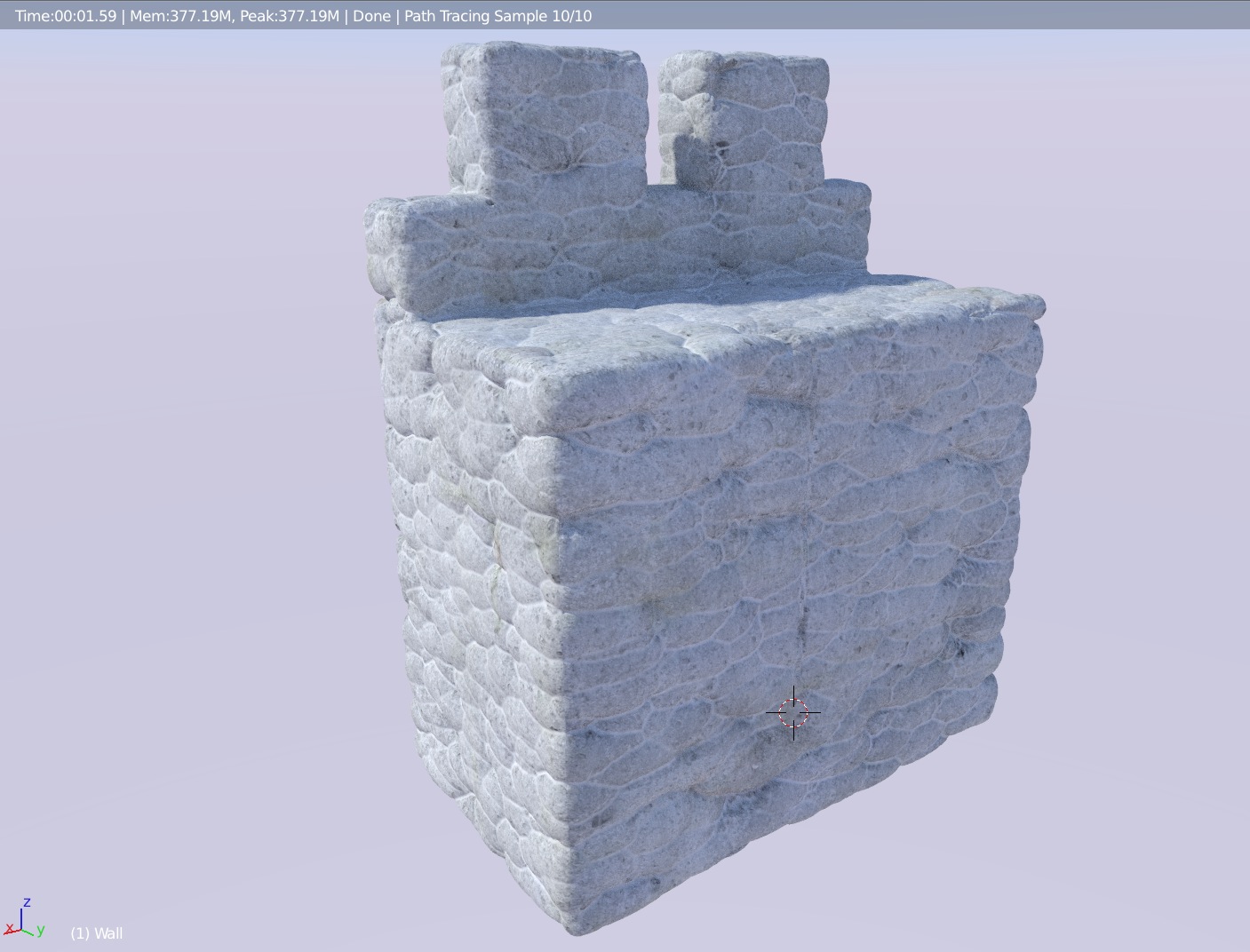
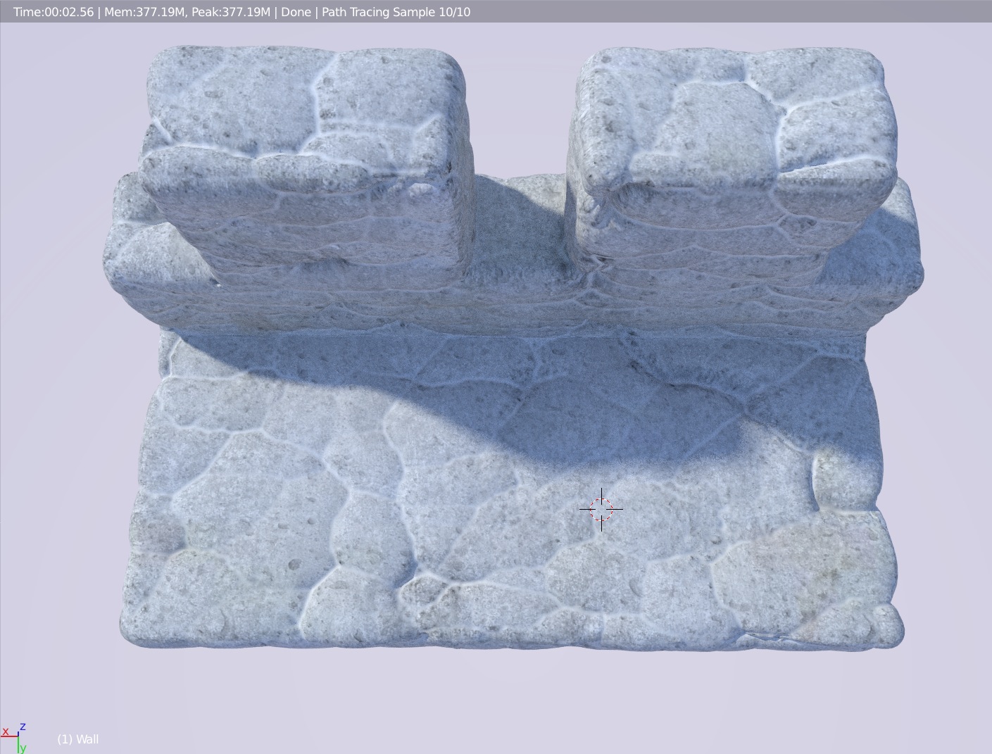
Then started the process of building the wall from the ground up, literally. As I was aiming at reproducing the natural placement of the stones in the wall, I started from the bottom aligning a row, then moved to the row above it and so on, trying to fill the gaps with smaller stones as a builder might do in real life. I must admit that my experience at building stone walls is minimal but nevertheless, my little real life experiment on the mountains of Switzerland wasn’t in vain, at least I like to think of it that way.

02Working with an eye on the reference pictures, I kept on constructing the wall but I choose to add slightly more randomness to the rows because of the only tiny bit of wall remaining on the mansio site where it seemed to be the case.

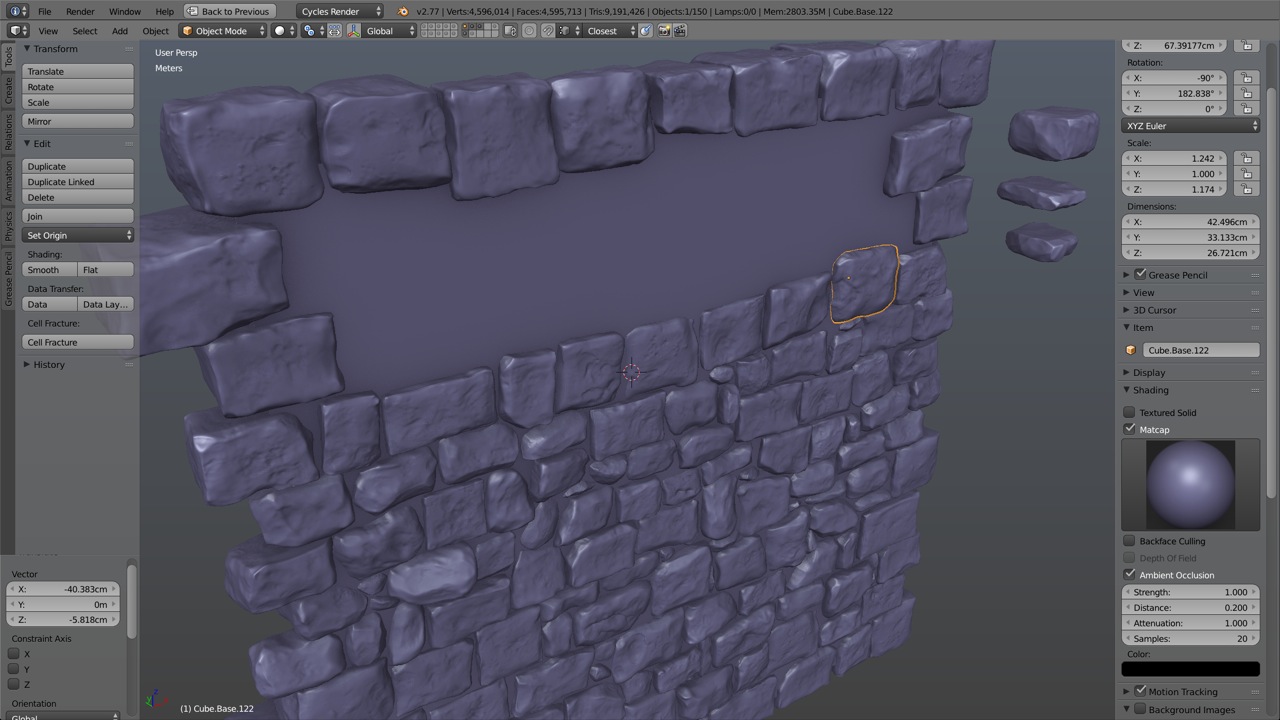
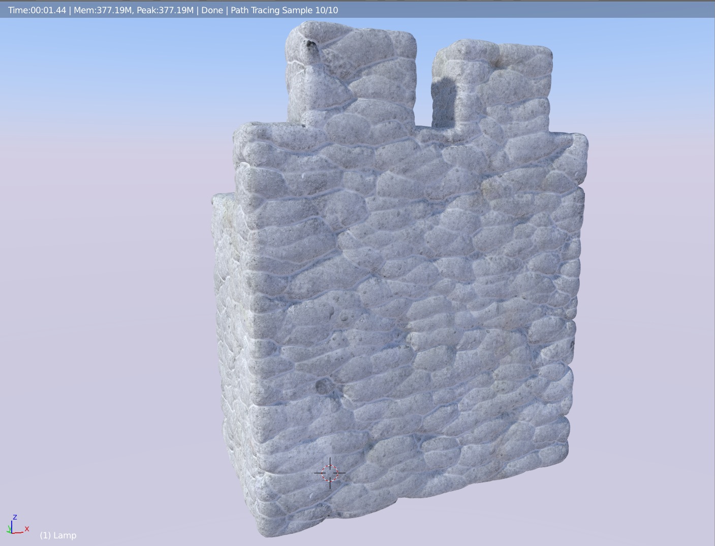
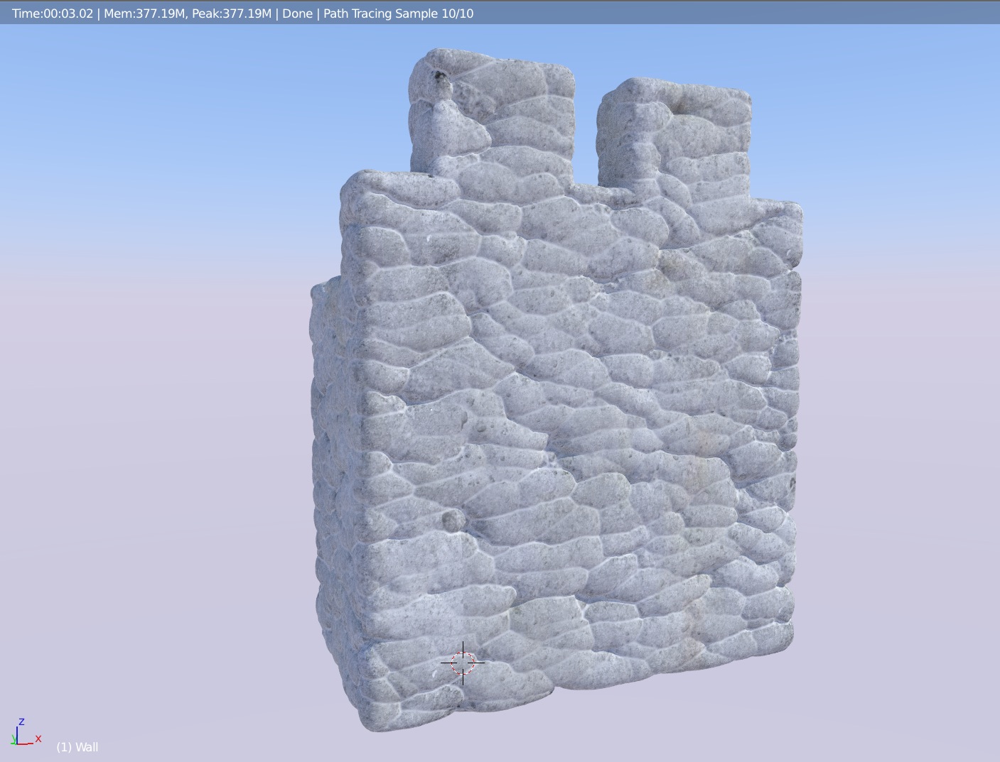
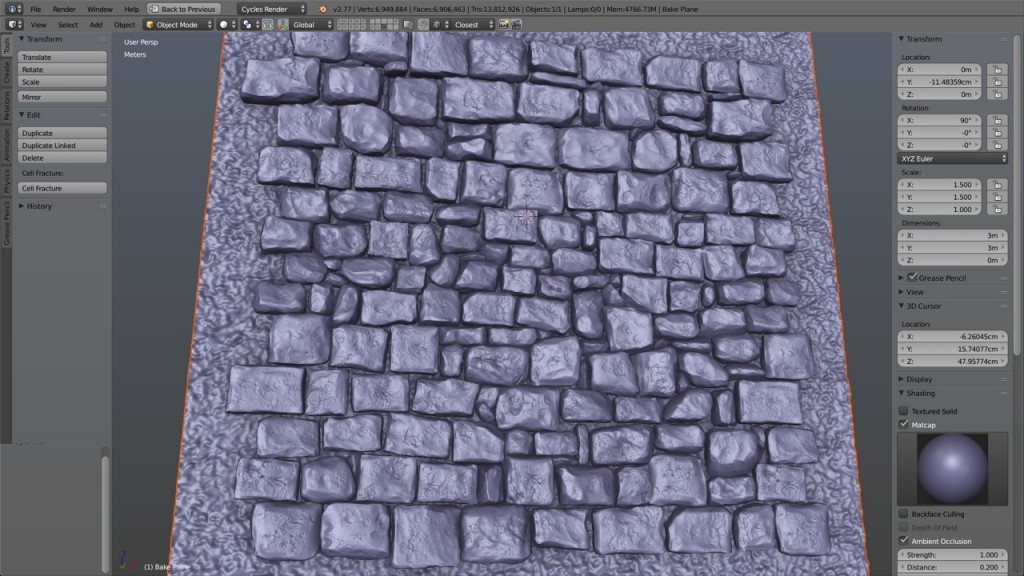
With the help of a simple plane, I levelled the front faces of the stones to give the structure an even aspect.

04
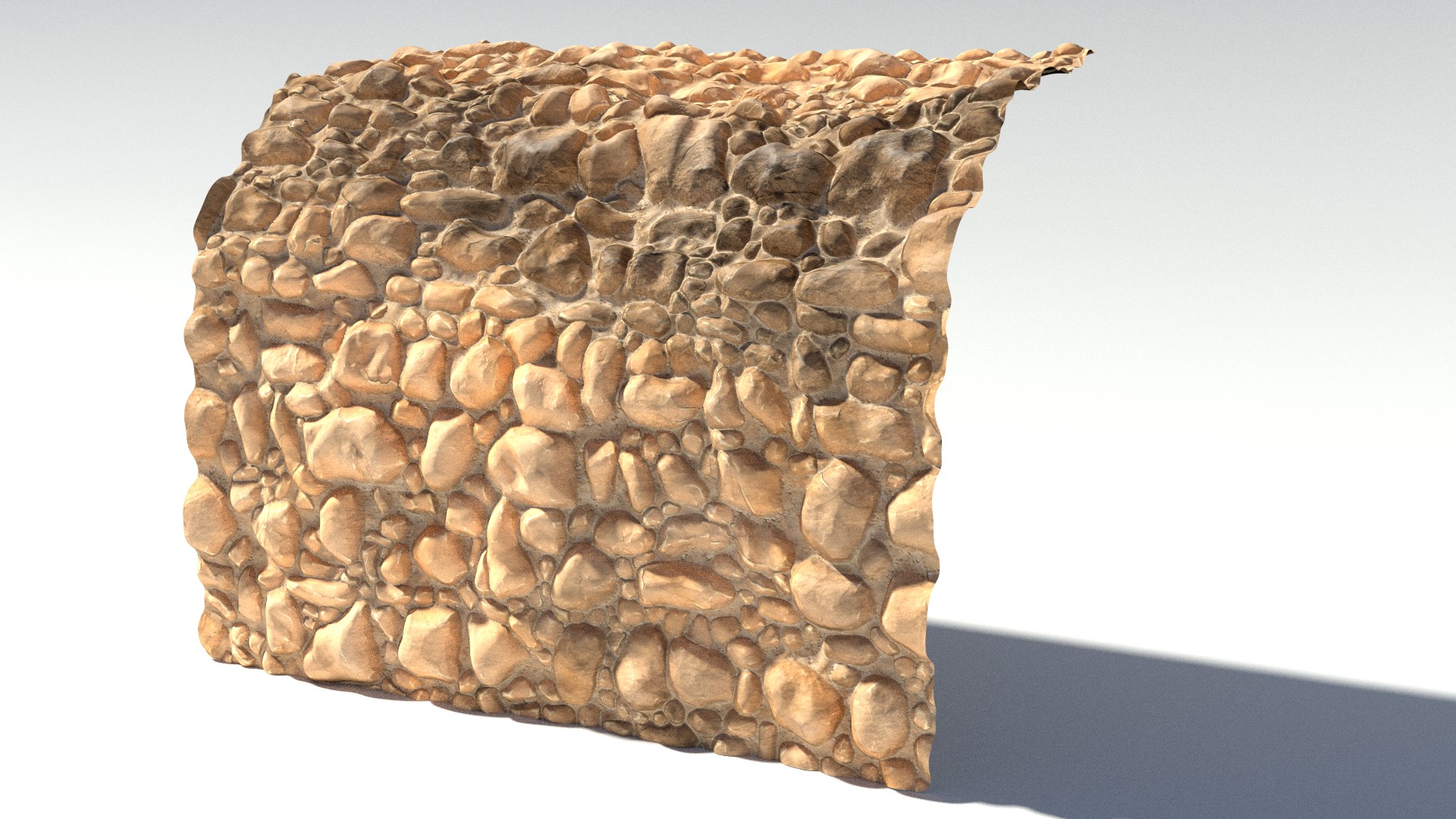
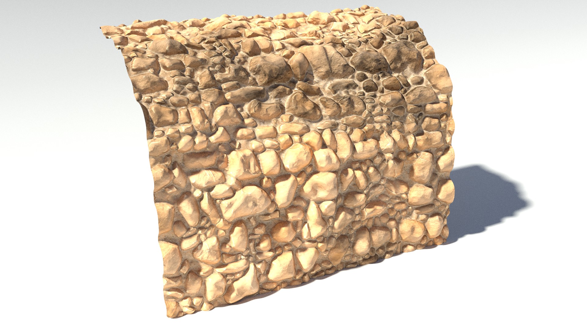
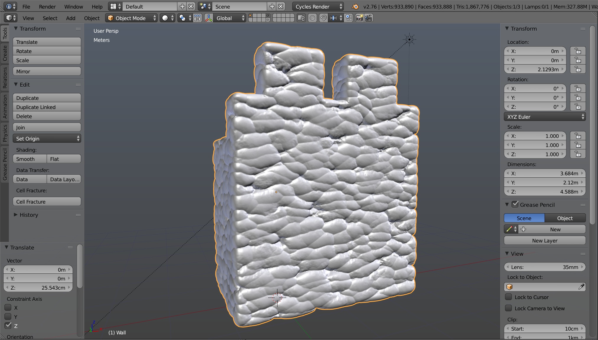
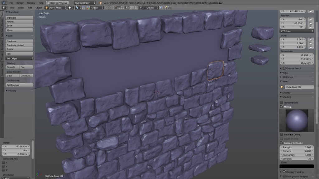
As I was missing a few stones to complete the wall, I went back to the sculpting process and a few stones later, here I was with my finished wall. Of course it is build to tile seamlessly. The back of the wall is completely unequal but who cares.

03
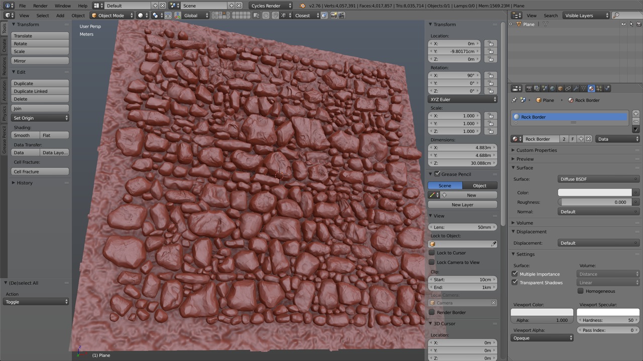
At this point, every stone was a separate object. This allowed me to place and make adjustments to the stones very quickly. However, because these were sculpts, the vertex count was quickly becoming very high. One way to avoid total meltdown of the computer is to keep the Multires modifiers and set the preview level to half or lower the resolution of the sculpt.

I already had a background plane for the seams between the stones, so I imported it and adjusted it to the proper size. Beware that this background has to be seamless too as some parts of its joining borders may be visible on the final texture.

05
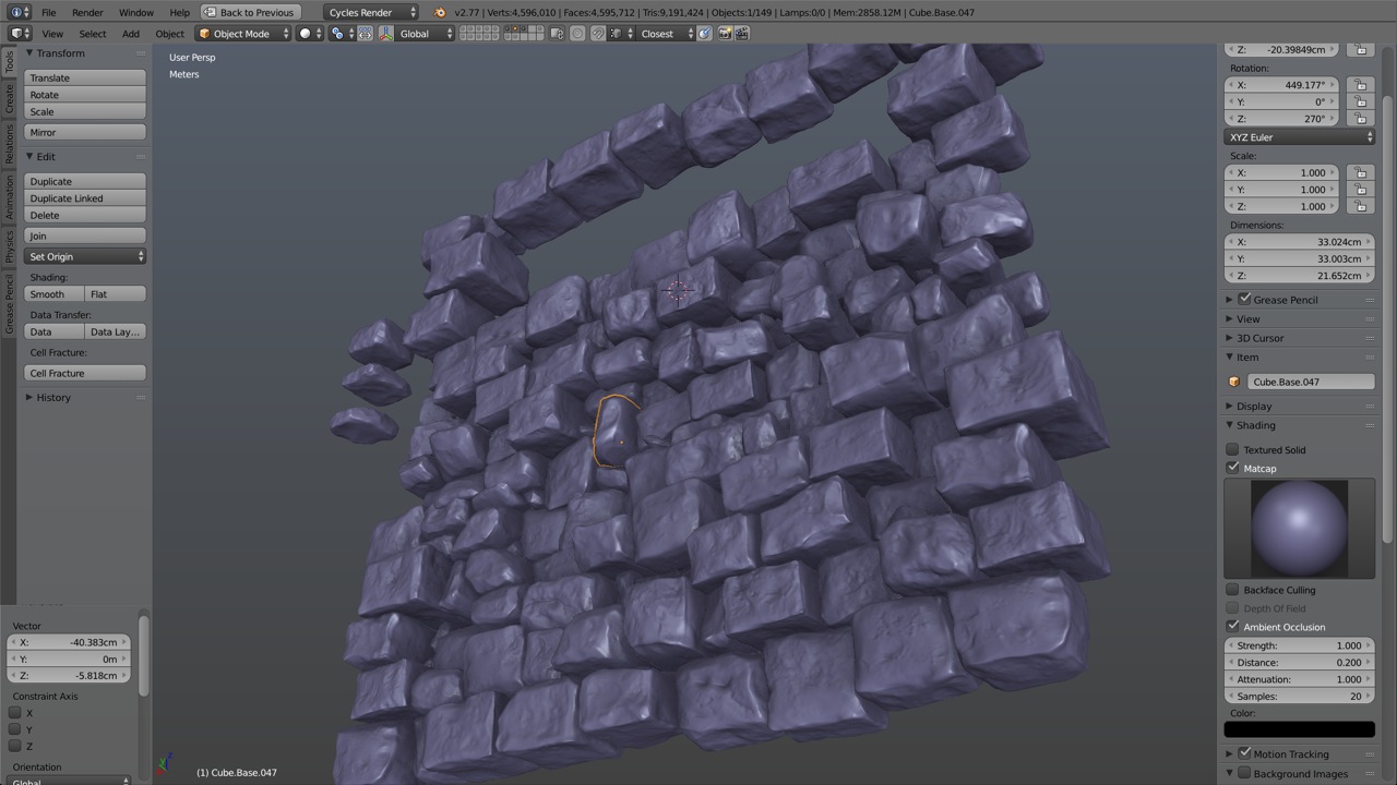
A limitation of Blender (the 3d software I use) is that it handles very poorly great number of separate object during the baking process. I found that I needed to join all the stones into one big object for any bake to complete successfully.

At this point, having applied all the multires modifiers with their maximum level of details, the polycount was just staggering, well at least for a 3 by 3 meters wall, reaching past the 19 millions vertices. Everything was slowing down as the computer struggled keeping track of all those vertices. Time to remove some dead weight. I deleted all the vertices behind the background plane and came back just under 7 millions vertices.

06
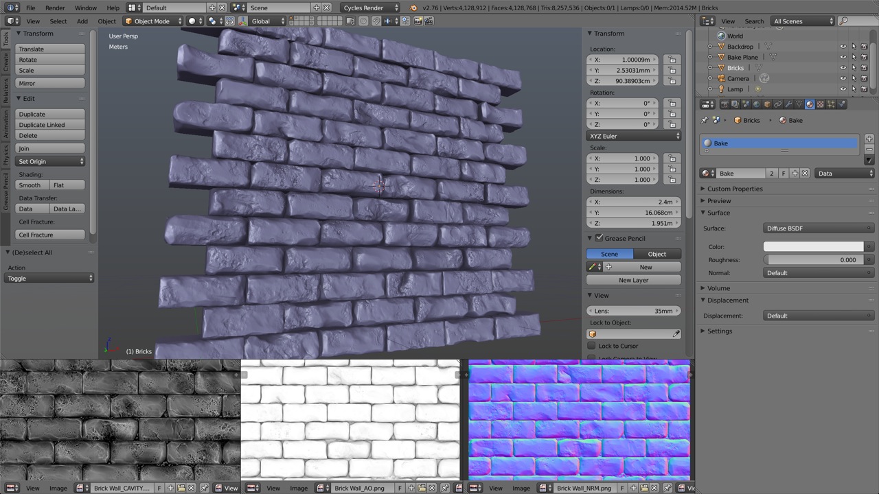
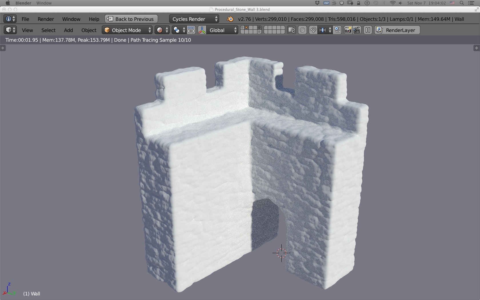
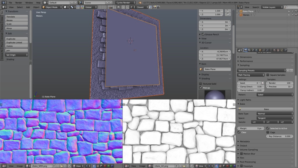
Its was then time to bake the normal pass followed by the ambiant occlusion pass. Too bad Cycles doesn’t yet support the height map pass, and I am too lazy to go back to Blender internal engine for that. It’s ok, I can load the normals into CrazyBump to get a decent height map.

07
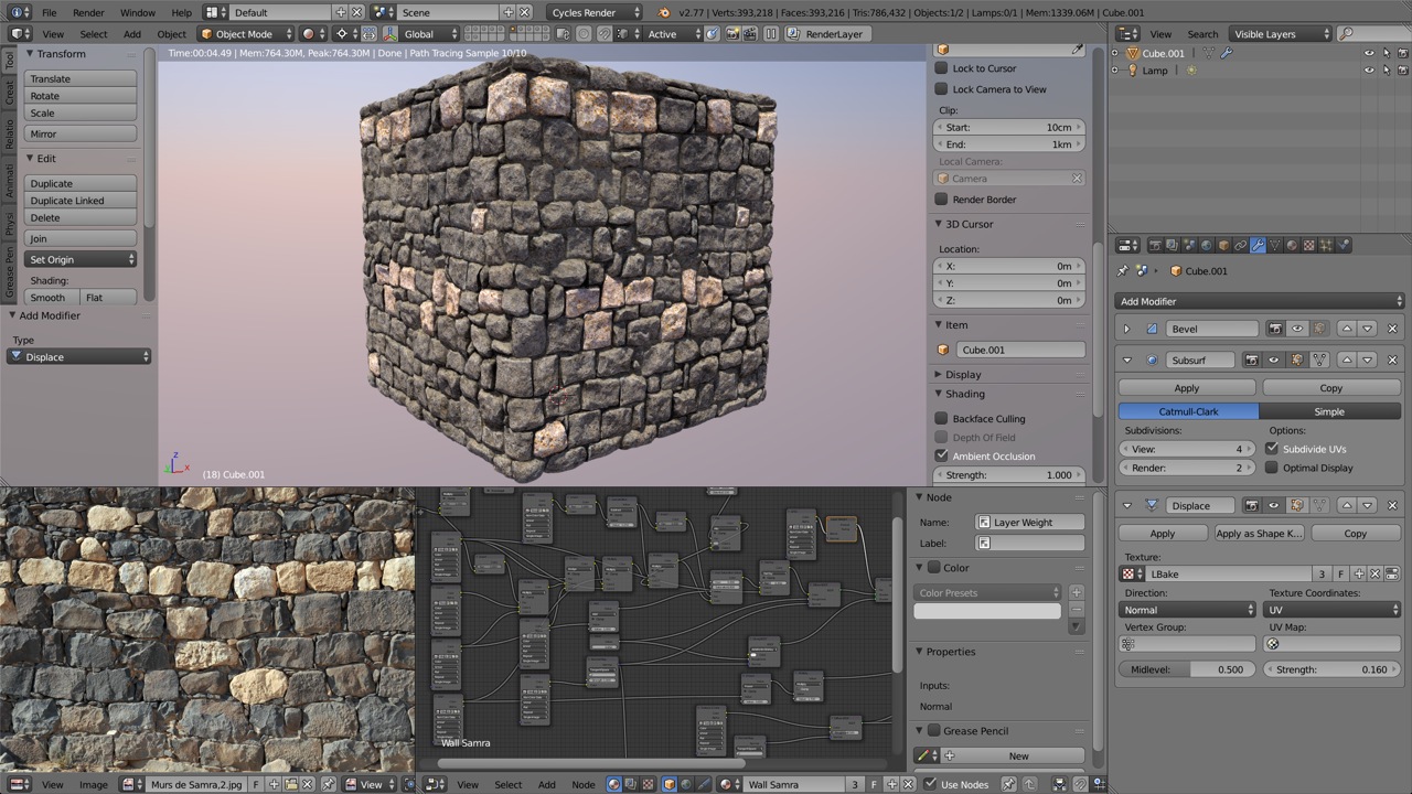
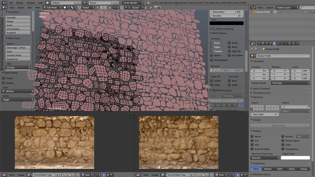
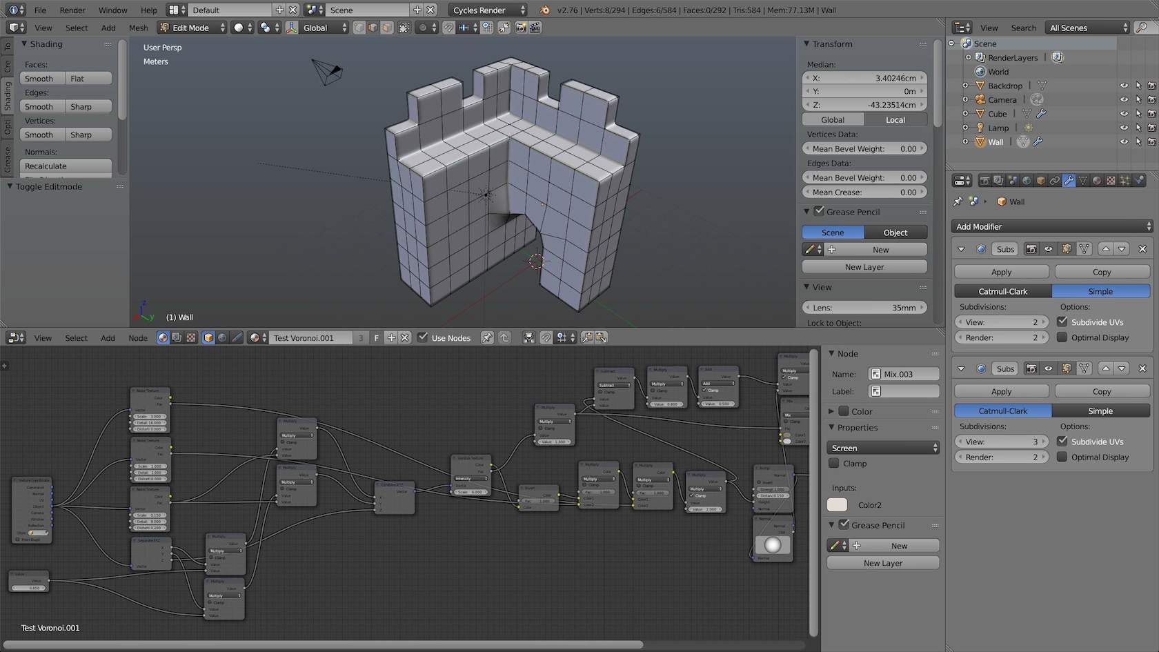
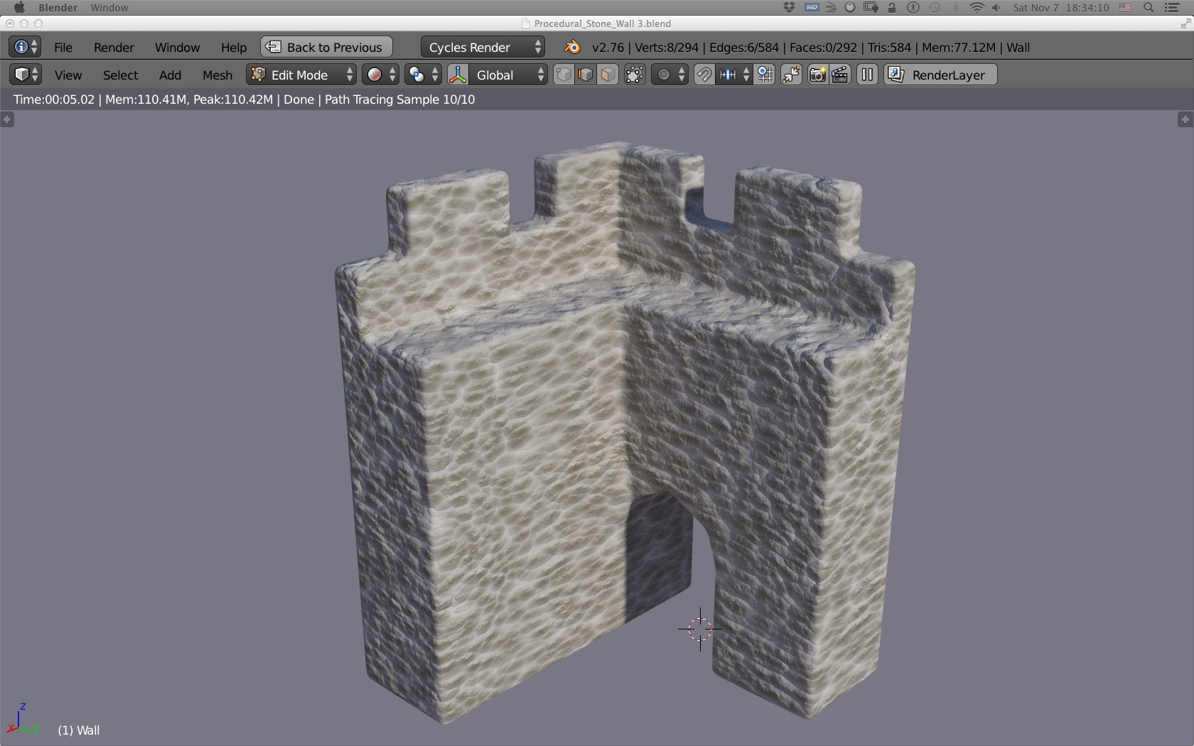
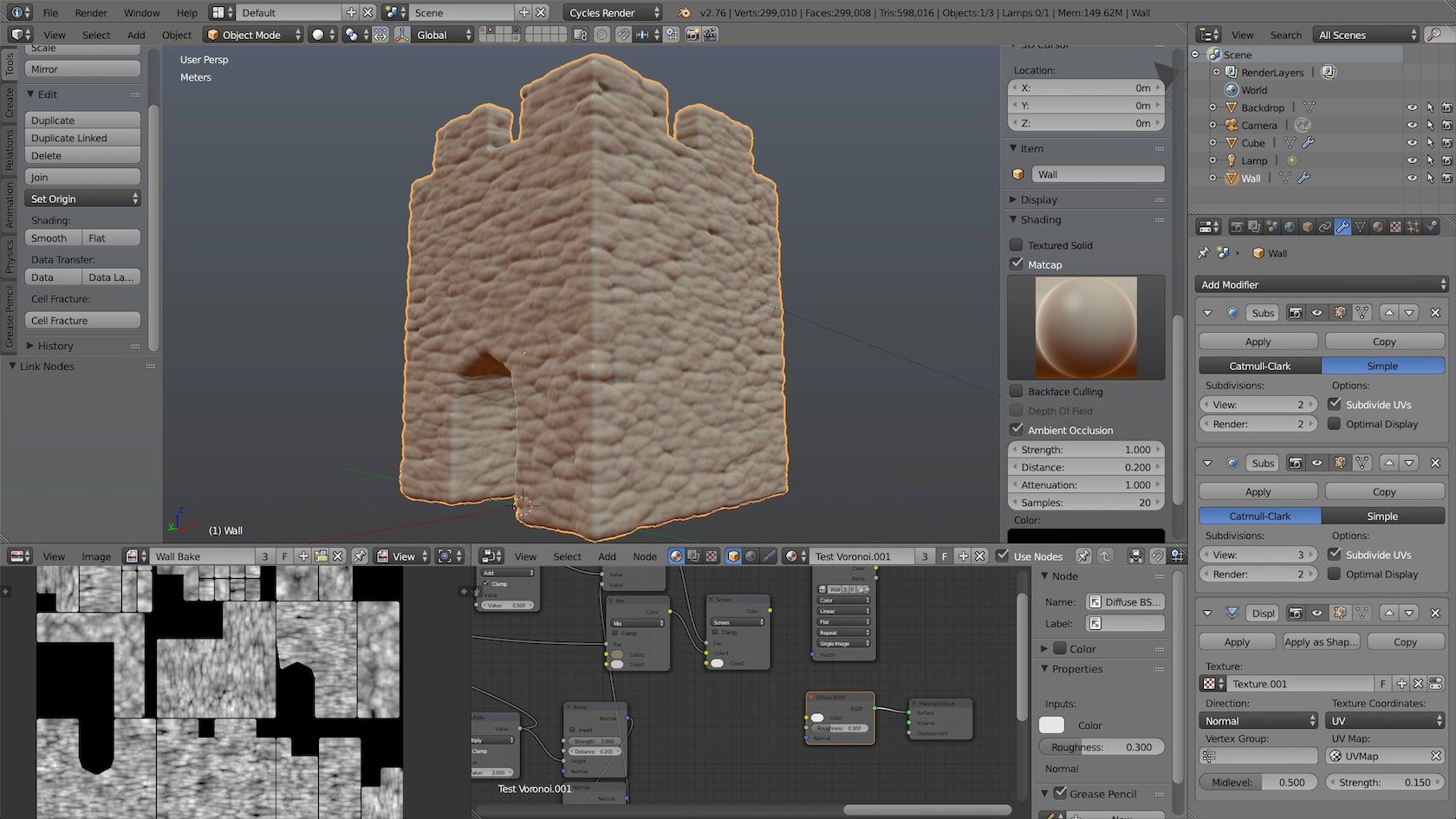
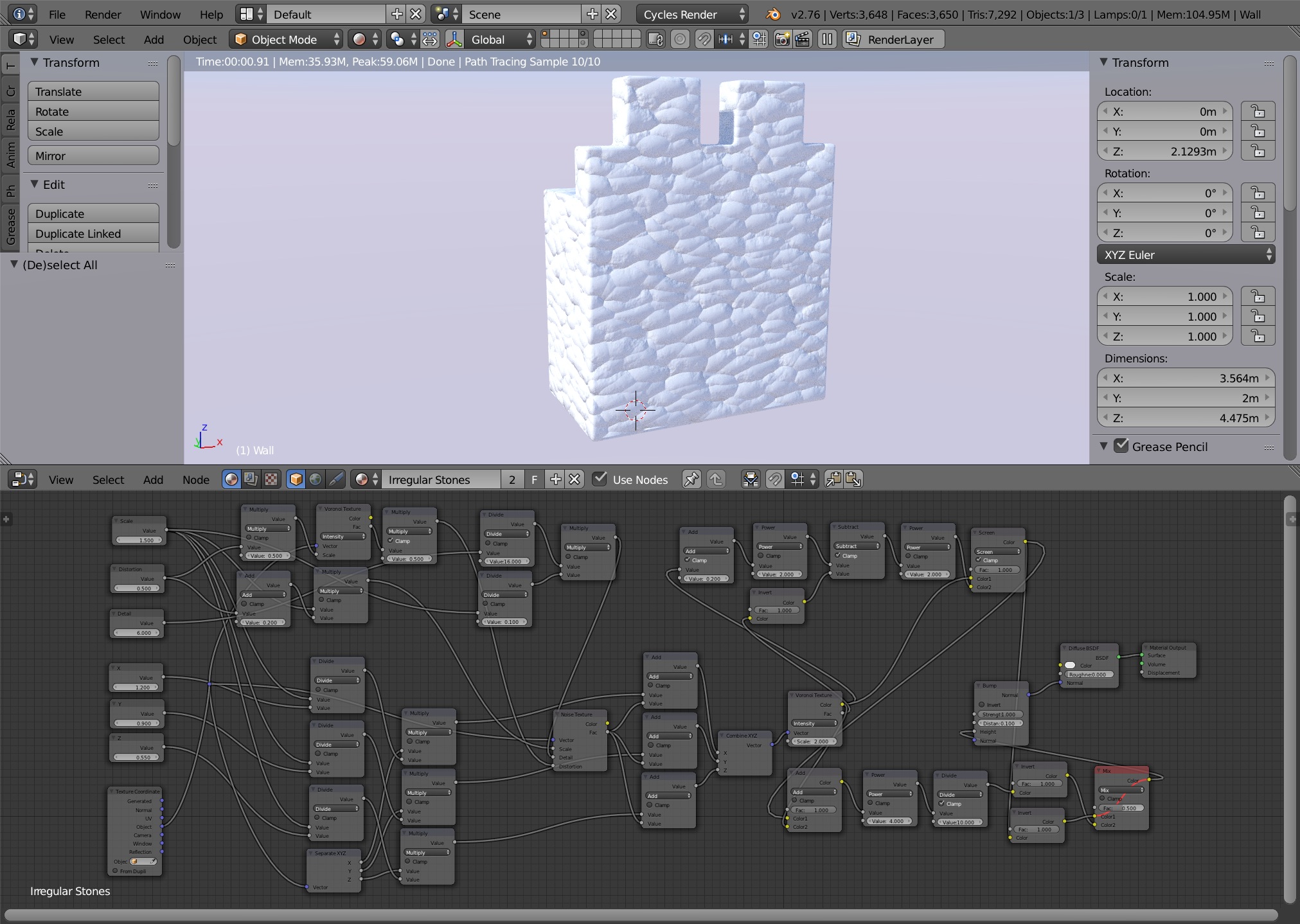
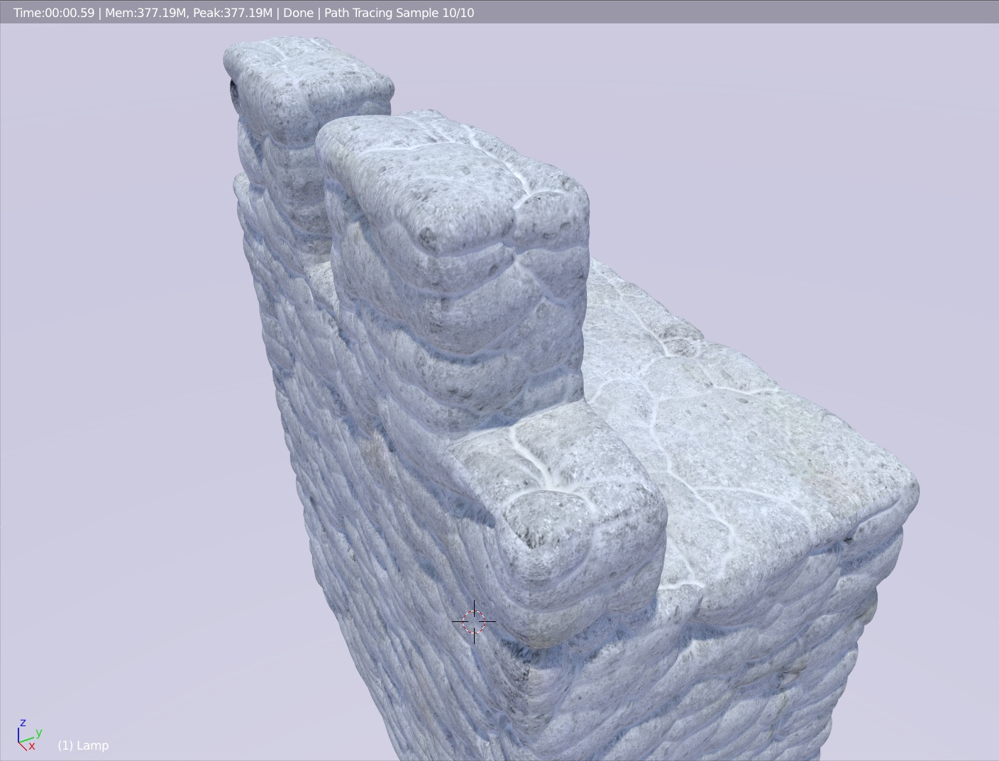
Having done all my bakes, it was time for a little material node cooking to test my new wall on a regular cube, here with some subdivisions and a displacement modifier and at the bottom left: the reference picture taken at Khirbet es-Samra.

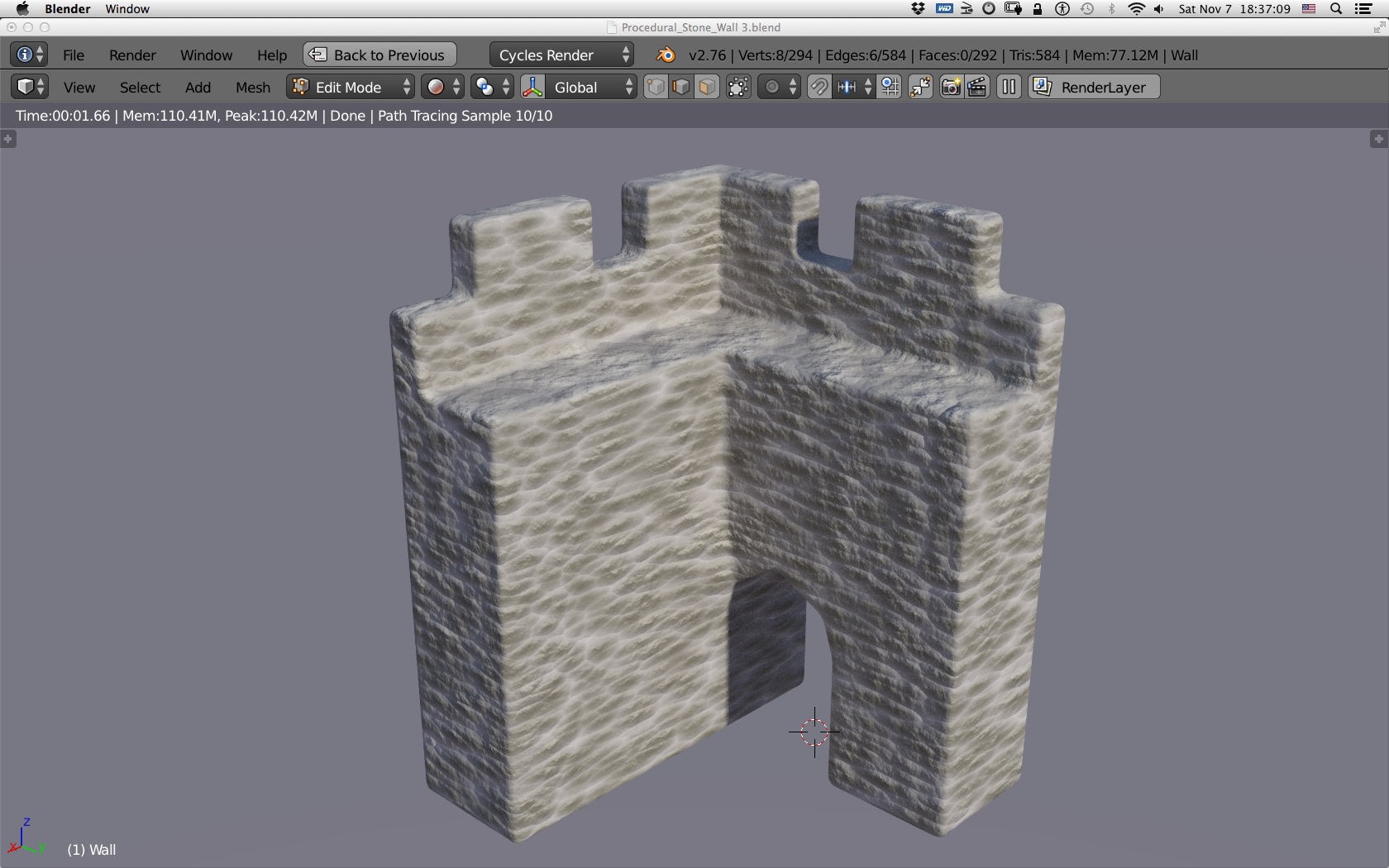
The albedo (color map) was made with a freshly shot set of pictures of some similar basalt stones from a different archeological site. The color variations were all done with material nodes.

What I have learned

If you don’t need to conform to a very specific stone profile, it’s quicker to model a complete stone and then use all of its six faces rather than sculpt five faces (front and sides) and not be able to use it for more than its front face.

If you make duplicates of a single object to use different portion of it (like the six faces of the stone), don’t wait until you have completed the whole project to decide to trim what you don’t need (like the back part of each duplicate). Make duplicates, rotate them as you need and then go ahead and remove the parts you won’t need before moving on to duplicating the next sculpt or model. Thus, you will always avoid reaching ridicule amount of vertices and your computer will always be more responsive.

It’s best not to sculpt the fine details like any stone decal brush or the like, because once sculpted in, you can hardly remove it and thus the sculpt is sealed. On the contrary, if you only sculpt the overall shape of the stone omitting the very fine details, you can always reuse the sculpt for different type of stone applying different finer details with decals or manually right before the bake. Thus creating different models with the same base stone, saving a lot of hard work and time.

Lionel

Qumran IIIA is on its way.

530 pages later…

After more than a year of hard work with Jean-Baptiste Humbert, we finally completed the publication that was in the making long before I joined the project. The complete book as been delivered to the publisher in Germany and is on its way first to the printer then to the bookshelves.

Qumran Volume III A Book Cover

It has taken a considerable amount of work to make it happen. Days and nights spent assembling all the material meticulously and in the end always the haunting of possible mistakes that crept in unnoticed. I can’t wait to see how it will be received by the Qumran specialists community.

Just a brick in the wall…

Testing some brick texture for the Qumran model.

Bricks in Qumran? Yes of course there are those buildings on the South-East whose brick-walls are still apparent to this day. But not just those. In fact many of the buildings, including most of the pools or reservoirs had almost certainly mud-brick super-structure. This is why many stone walls are so uniformly levelled, they were the foundation upon which the upper most structures made of plastered mud-bricks–that didn’t survived time and weathering–stood. Well, at least not in their initial form since in fact their debris filled the site to the point where it was barely visible when archeological digging started in the 50’s, apart from the famous so called tower whose top was above the ground.

So, following the same method used for the stone walls, I started creating some brick shape only this time it wasn’t necessary to use photo reference to model the shape since a brick  is, well, a brick. Only the scale mattered in this case.

Qumran Bricks Sculpt Test 1

Once the tillable brick wall was sculpted, baking the normal map, AO and height map was done. Then, with help of photoshop, I made a cavity map that will help later on give some extra definition to the color map in the shader.

This is the result on a cube with a simple shader using normals, specular and height map for mesh displacement on a subdivision modifier.

The corners are not addressed here as the bricks simply continues from one side to the other without angle consideration which should ultimately show the actual width of the brick and not the next brick. Something I need to consider.

Qumran Bricks Sculpt Test 2

On a continuous plane, the texture is perfectly tillable. With the help of an extra layer of noise displacement on top of the actual brick displacement, it becomes even closer to the originals. I may have to adjust the scaling of the texture to better fit the reference material.

Qumran Bricks Sculpt Test 3

Next thing, I will have to dig in my Qumran photo library to find color reference and adjust the texture color to match real bricks. However this is rather not so critical since almost all the time, it will be shown covered with plaster.

Qumran Archeology

Building a 3d model of Khirbet Qumran.

I am not the first nor will I be the last to attempt a 3d reconstruction of Khirbet Qumran. However,  all that has been made available to this day on the subject is somewhat incomplete and either partly inaccurate, fantasy or subject to strong questioning. Therefore, working with archeologists to reconstruct what the site of Qumran might have looked like was a challenge that I could not pass by.

The first thing was to build the main structures of the wall and loci. That was the easy part since it is basically just redrawing the map of the site and extruding to provide elevation. That is where problems arise. First, we don’t know how tall the walls were, nor do we know with certainty how many levels there were in the buildings. Then, an other problem comes along which I believe has largely been either ignored or underestimated: the ground is uneven and there is a slope going from West to Est on the site, which means not all ground-level buildings are at the same elevation. This is evident to any observer on the site, but on the computer or on paper, it is often not shown or discernible. This might seem trivial but it is extremely important to the volume reconstruction of the site as adjacent structures do not necessarily nicely align horizontally as often imagined from looking at the plans. The whole reconstructed aspect of the Khirbet must therefore take this into consideration.

Texturing the model.

Early on, I was asked to provide some illustrations from the work in progress and was confronted with the difficulty of texturing the model. Relying on generic rock or stone textures definitely was not a nice option. What else? Paint the photos of the real stonewalls themselves on the model? Very hard to do if possible at all given the number of pictures it would require, not mentioning that most walls are now long gone. I choose to try something in the middle: create a generic texture but from the real material. So I went back down there (some 450 metres below sea level, and no I didn’t have to dive) and started shooting some reference pictures.

Back at home, using the photos as guide, I started the tedious process of recreating the stonework in Blender to build a 3d model of a portion of the wall.

Screen Shot 1

Once the stone themselves where built, I removed the seams and a duplication of the whole area made the process of checking the tiling of the pattern easier.

Screen Shot 2

Then, extruding, subdividing and sculpting took place. Very lengthily process as I had to sculpt every stone individually but in the end the result is quite acceptable I think. It could still be improved, but as a first shot, that’ll do for now.

Screen Shot 3

After this, it is just a matter of baking the normals, height map and ambient occlusion to give me a good starting point for building a tillable Qumran wall texture.

Now this is what it looks like with some experimental shader on a mesh with a displacement modifier.

texture wall 8

texture wall 7

Of course, it would be difficult and prohibitively resource intensive to apply mesh displacement on the entire model and this method is exclusively reserved for closeups shots. For far away shots, normal map will usually admirably fit the bill. This is what it looks like (with a slightly different shader) on an early and incomplete model of the Khirbet. It does not yet incorporate the terrain of the site itself but I’m working on it.

Model Preview 36

The work got started some months ago but was interrupted by other works underway that engulfed all my available time. As this diversion is coming to an end, I will resume my work on 3d Qumran momentarily.

Will we manage to produce a viable proposition of a reconstruction of the site? Time will tell.

Procedural journey in Blender II

While thinking about how to break down the shapes of the stones from my previous attempt, the natural thing that came to my mind was, as usual, the noise texture node. So I fiddled quite a bit with it today and here is the result.

I started from scratch and decided to make it simpler than the previous attempt, that is without all the mechanic that makes all the process scale together in relation to each other. I was going for a quick way to test the deformation of the voronoi blobs, and basically, once again as almost always, a noise texture node is your best friend. Applied to the voronoi coordinates input, it works great given the right values, and to add more variance, add more noise with different values that you can layer on top with a mix node.

The model is nothing special but it will demonstrate the tilling capacity of the procedural texture, here exclusively used as a bump map, and its consistency over the entire model.

Screen1

The mesh has no UVs, all is procedural.

Blender Stone Wall 1

The texture is a simple two colour combination with the height map as a factor. I added a third light colour in Screen blending mode on top with the up vector from the bump map as a factor. There is also some subdivision modifier to break the corners in order to better see the propagation of the procedure.

Blender Stone Wall 2

When stretched over the x and y axis, some areas starts getting problematic, but overall, it not too bad.

Blender Stone Wall 3

The last version is the same model but with only a white diffuse colour map and a displacement modifier based on the baked procedural height map applied on five levels of subdivision surface modifier.

Blender Stone Wall 4

And here is the model with subdiv, matcap and AO in the viewport. Under, the baked height map on a generic Smart UV Project, which is being used by the displacement modifier.

Screen2

Cheers.


Procedural journey in Blender

For quite a long time I have been looking for a way to create some stone wall texture procedurally. I’ve spent hours upon hours trying to get some decent result in Blender, using the node system in Cycles. Alas, all the results I was able to achieve so far were poor, unrealistic, unpleasing and mostly impracticable.

That was until today, when I had that kind of eureka moment where I thought of an alternate approach to the method I’ve used so far in that project. It’s a breakthrough in my endeavour to come up with a usable way to procedurally create some stone wall texture and most importantly : its displacement map.

Unless you paint it, it won’t match perfectly.

The difficulty with stone wall is that any edges, door, window or junction will inevitably produce difficult area for texture matching. Hence, the coherence of the structure is very much disturbed when stones don’t seem to fit properly on the corner of a wall or when it doesn’t match with the top or side surfaces. Of course you can always spend a lot of time, and I usually do, to try to unwrap the volume with the best match possible but it is mission impossible unless of course all the textures have been specifically made for that particular mesh. So unless the project you are working on has enough time and resources budgeted, most of the time, creating 100% custom textures all over the place just won’t be always possible.

Here comes the procedural magic.

The beauty of the procedural process is that it is consistent across all the model because it is volumetric (at least in the case of this example) and it is also extensible and none repetitive if you setup your procedure properly. No matter where you cut, punch or joint your mesh, the pattern will always be matching with very few problematic areas. There are of course some limitations but it is mostly fool proof and for the most part far superior to most unwrapping techniques, no matter how sophisticated, in my experience at least.

Did I say none repetitive? Yeah baby, that alone is a big seller. Endless variations with mostly endless boundaries. No more seams, simple as that. Moreover, if you setup a procedural texture that is well designed, you can typically use it in many scenario, hence a huge time saving bonus later on.

There is a big drawback though : it can be very processor intensive. So no real time here. At least not in its raw form. But you can always bake your procedural texture and then apply it for some real time application if need be.

Not quite there yet, but much closer than I have ever been.

Ok, I must admit that the results aren’t totally satisfying. The stones look a bit bloby and I am still unable to control the size of the groves between the stones. Yes there is still a lot of work to make this really helpful. However, I can set the average size of the stones on the three axis separately and in general as well as the amount of roughness detail and distortion.

What about the stone wall?

Well, here it is with the procedure applied as a bump map. It’s black and white because my goal was to produce a height map that I could then bake and use with a displacement modifier (since vertex displacement is still experimental).

Nodes

The mesh is a very simple one with very few vertices and just a diffuse white. What appears to be in volume is simply the procedure being feed through a bump node to the displacement of the shader output.

Now, this is the same mesh with tons of subdivision and the baked procedure map in a displacement modifier.

Wall1

The same mesh in the live viewport preview with a simple material : a couple of colour map mixed with the cavity map factor. Nothing fancy, just to preview the effect of the displacement modifier.

Wall2

As you can see, there is no seams at the corner and most importably, the stones have a coherent continuation at the corners and on the top.

Wall3

Wall4

The stone are larger on the x and y axis than on the z axis. This produces a quite pleasing effect on the top of the structure where usually stones are larger to cover more space.

Wall5

The seam visible here is simply that of the colour map I slapped carelessly on the model, not of the stones themselves.

Hopefully, I will find some time to continue develop this and maybe make it better so one day, I won’t have to spend hours sculpting every freaking stones to produce a decent normal map or height map.

Cheers.

Working with archeologists…

Through an acquaintance, I’ve had the chance to meet archeologist Jean-Baptiste Humbert about two years ago. We quickly developed a friendly relationship and one thing leading to an other, I’ve been working with him for the last two years doing various 3D illustration projects and other graphic works.

When I was asked to give him a hand to finish one of his most important project, namely the publication of the third volume of the excavations of Khirbet Qumran, I jumped in not really knowing how much work and effort it would require from me. That was several months ago, and at that times, it seemed like the project was almost completed as Jean-Baptiste and a few other people had been working on this project for many years already. Since then, I’ve been working like a horse to pull all the remaining tasks to completion and it’s been quite a ride, and a tremendous amount of work. Spending days and nights, at times sitting side by side with Jean-Baptiste, in front of a row of computer screens, checking layout, hundreds of rows of reference numbers, drawings, photos, adding, removing, correcting, creating…

Then going back home, continuing the work well past midnight and going back again, a few days later, to meet with Jean-Baptiste and review together the corrections. Sending the text for proofing, getting it back, making some changes again, sending it again. It’s been months of work now and while there seem to be no end to this process of corrections and improvements, we are finally reaching the end of it.

From what I understood, there is a great deal of interest in the archaeological community regarding this publication, and probably some weariness regarding its constant delaying. We work hard to bring this work to completion and I dare hope my intervention in this process will be beneficial both to the reader by providing a volume that is pleasant to read and consult, and to Jean-Baptiste by helping him producing a book that will translate his work as best as possible.

In the meantime, I get back to work.

Making a medieval town and castle in Sketchup (part VI)

It’s been a while and I almost completely lost track of that project. I moved to an other country, my eldest daughter graduated this year, I got plenty of work on the waiting list and Sketchup was way outside of my radar lately until I got a message from someone, which might not be a spam for once, saying that he liked my posts. Well, that kinda surprised me a bit at first and got me to open the file and look at it again. I noticed that I made a few more additions to the model since  its last submission and so, despite being busy on several other projects, I thought why not at least post a few screenshots of the latest stage of the modelling. Nothing fancy though, but hey, since it’s done and apparently some people are taking interest in this, I guess it wouldn’t hurt anyone.

While I mostly work in Blender 3D now, I still enjoy Sketchup now and then for quick prototype and above all, for real shadow projection. Mind you, this feature alone is brillant if you have to deal with real architecture. For instance, you could preview the kind of sun/shadow coverage you can get on any given building with the help of Google Earth, for the whole year. This is great if you intend to buy a house or property, make renovations, study a reconstruction of a structure or archaeological site.

So here’s the model where I left it some years ago.

Ville Step 3.8.1

Ok, not much has been done since the previous post I admit but I’ll still give you a few screenshots.

Ville Step 3.8.0

The gate and the fort were connected by walls. Now I need to connect the fort to the citadelle.

Ville Step 3.8.2

Some houses got a roofing upgrade. I initially intended to model each house separately and import them back in the city model and started a couple of them but I quickly feared I would not have the time nor the courage to proceed with everyone of them. So I went for a quicker method of just modelling the silhouette.

Ville Step 3.8.4

A wall has been added behind the citadelle to protect the poterne. I think I will have to close the gap and put a passage instead of just leaving it open, although strictly defensively, it wouldn’t make much of a difference given the massive fortification that covers the passage.

Ville Step 3.8.5

Of course the poterne will eventually need a ramp to be accessible.

Ville Step 3.8.6

Here’s a house I’ve been detailing a little bit to give more interest to the square. It’s not a lot I admit but from far away and if all houses are treated the same way, once it’s textured properly, it could quite sell the shot.

Ville Step 3.8.7

A view from the tip of the citadelle looking towards the fort in the background. I just see now that one of the crenelation is larger on the foreground and I remember I intended to put in a machicouli because if I remember well, it is right above the entrance of the bastion. An other one of those “I’ll do that later” moment I guess.

Ville Step 3.8.8

While I put some doors in the square towers, I noticed I did do that for the round ones, I guess the complexity of the geometry of the curved wall put me off at the time, but it should be dealt with at some point. Those kind of small details have the incredible power to give life to a model by attracting the eye and giving a sense of scale to the whole scene.

Ville Step 3.8.9

That’s it for now. If you like it, just let me know and that might stimulate me to find the time and energy to continue the model.